REPOSAL® Winding machine Optimum design of CNC winding machine for large power transformer
Optimal design of CNC winding machine for large power transformer
In the manufacture of power transformers, winding the transformer coil is a super important step, you think, the transformer coil is wound more firmly and neatly, the strength of the transformer and the ability to protect against short circuits can be greatly improved. However, most of the current transformer winding machines have to rely on manual extra sorting of the coil, the entire equipment is low in automation, and the production efficiency is not high, so the development of an excellent large transformer winding machine is a crucial thing for our company.
![]()
We have studied the main shaft technology of transformer winding machine, the relationship between compaction force and winding quality, and the control of compaction force. According to the principle and process flow of transformer winding, we put forward a whole design scheme of large transformer winding machine, including mechanical structure and electrical control. Mechanically, we simplify the complex structure of traditional transformer winders. In terms of electrical control, we ensure the stability of the motor when it starts and stops, and ensure that the winding coil is evenly tightened during the winding process. For the core parts of the transformer winding machine, spindle system and pressing device, we have calculated and selected the types and parameters. With the compaction device, we are able to provide real-time axial and radial compaction forces during the winding process of the transformer winding, which is very effective for improving the tightness of the winding.
The static analysis of the radial compaction device of the winding machine is also carried out by using finite element method, and the structure optimization is carried out according to the analysis results. We find that as the number of layers and turns of the winding increases, the required axial and radial compression forces change accordingly. By analyzing the experimental data, we find that there is a maximum value and a minimum value in the range of quality requirements, and it is the most reasonable choice to make the compression force approximately proportional to the number of layers and the number of turns.
The large transformer winding machine developed by our company has been preliminatively debugged and put into the market. After testing, the performance parameters of this transformer winding machine are in line with the design requirements, and the operation is stable and efficient. It can be wound to make a tight and regular transformer winding coil, and has been fully recognized by the market.
As a power grid equipment, power transformer converts voltage through the electromagnetic induction between the winding coils of the transformer. With the continuous development of the market, higher requirements are put forward for the manufacturing level of transformers, and the market needs more energy-saving and efficient transformers. Therefore, the optimization of the transformer manufacturing process is particularly critical. Quality and performance depend on the process equipment. The technical level of the transformer winding machine directly reflects the manufacturing level of the transformer. Therefore, accelerating the development of transformer winding machine is an important guarantee to improve the performance of transformer.
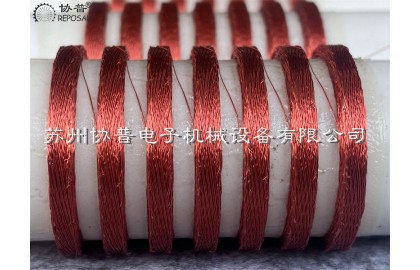
The winding coil of the transformer is the core component of the transformer and constitutes the electromagnetic induction part of the transformer. It generally includes high voltage winding and low voltage winding, respectively connected to the high voltage grid and low voltage grid. The winding of large power transformers usually adopts concentric winding, that is, the high and low voltage transformer winding coils are centrally set on the core column. The manufacture of transformer winding is the core process of transformer, and its quality plays a crucial role in the performance of transformer, affecting the appearance of transformer size, weight, mechanical properties, insulation and heat resistance and other important indicators.
In the past, the production of transformer winding coils relied on manual, and workers had to wind insulated wires manually to the winding die frame in accordance with the process requirements. Turns calculation also have to rely on manual, this old-fashioned method is inefficient, and because the worker's skills are not strong enough, the quality of the winding coil is poor, the number of turns may be miscalculated or missed, and ultimately lead to the finished winding coil performance can not be guaranteed. Later appeared semi-automatic transformer winding machine, which is driven by the motor to rotate the spindle to wind the transformer winding coil, although it improves the production efficiency, but the wiring work still has to rely on manual, only suitable for flat winding transformer winding coil winding, and winding head winding, welding and other operations must still be completed manually, so the product quality is not stable.
Later, with the emergence of TTL logic gate circuits, in the mid-1970s, with the development of CMOS technology, various types of equipment program control a large number of applications of digital integrated circuits, Western countries and Japan and other industrial powers have emerged CNC winding mechanism manufacturing industry. These CNC transformer winding machines represent the advanced level of winding mechanism manufacturing technology, especially the winding equipment produced in Japan, Italy, the United States and Germany is the leading technology.
Now the transformer winding machine as the core parts of the transformer production equipment, the market demand is very large, and the transformer manufacturing enterprises at home and abroad attach great importance to the development and application of advanced technology of transformer winding machine. Domestic transformer winding machine production enterprises are small, insufficient technical reserves, limited research and development funds, so there is still a big gap compared with foreign advanced products, the market share is low, unable to compete with foreign countries. To solve the key technical problems of transformer winding machine is the key to improve the quality of domestic winding equipment and enhance the market competitiveness. In order to meet the demand of transformer manufacturers for high quality and low price winding equipment, especially large transformer winding machine, on the basis of learning from foreign advanced experience, combined with domestic research results, the development of large transformer winding machine has important significance and practical value.
![]()
The research of transformer winding machine in foreign countries started earlier, there is a rich accumulation of technology, and the research of winding mechanism and the design of transformer winding machine have been very mature. Japan, Italy, the United States and Germany and other countries of the winding equipment is particularly advanced, their high degree of automation, excellent performance, favored by users. The transformer winding machine and supporting equipment in the United States have perfect human-machine interaction platform, beautiful models, convenient program control, flexible equipment, and are suitable for winding transformer winding coils with complex shapes and high precision. These countries have their own core technologies, but as technical secrets are protected, these key technologies mainly include spindle technology, high-precision wiring technology, tension control technology and so on.
China's research on winding equipment started late, began to introduce foreign CNC transformer winding machine in the early 1980s, and gradually entered a stage of rapid development in the 1990s. In recent years, the domestic transformer winding machine industry has formed a certain production capacity through independent research and development and the introduction of foreign advanced technology. But most manufacturers are small, making it difficult to enter the high-end market. Compared with foreign advanced products, there are obvious gaps in control technology, update speed and new process application, resulting in a disadvantageous position in the competition and unable to resist the influx of imported products. Therefore, on the basis of actual production experience, the domestic industry has put forward a more perfect transformer winding machine design scheme from several key technical points.
The first is the spindle technology, which involves the headstock, the drive part and the transmission part. As a core component, the spindle is used to transmit power and perform actions, while the headstock is responsible for supporting the high-speed rotation of the spindle, which must meet the requirements of simple structure, reliable work, easy maintenance and low cost. The spindle system in the transformer winding machine is different from the general purpose machine tool. In the winding process of the transformer winding machine, the spindle needs to be started and stopped frequently. If the spindle system is not stable, the tension of the winding coil will be unbalanced, resulting in uneven tension of the transformer winding coil, which directly affects the performance index of the transformer.
![]()
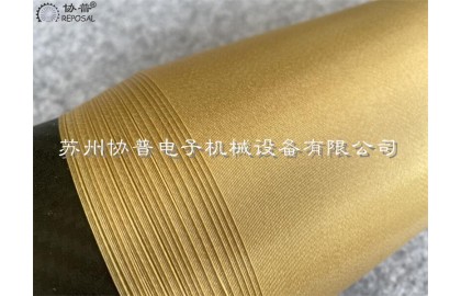
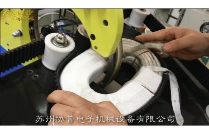
The second is the radial compaction device, and the appearance size of the transformer winding coil has a great influence on the performance of the transformer. If the winding coil axial size exceeds the standard, it will weaken the transformer's ability to withstand short-circuit mechanical force and reduce the short-circuit resistance. The excessive size of the winding coil will lead to a large deviation of the transformer impedance parameters. For large transformers, the winding coil produced by the ordinary transformer winding machine, because it can not apply any pressure, it needs to be beaten and shaped manually, resulting in a large error of the winding coil, affecting the performance of the transformer and increasing the consumption of raw materials. The compression device can provide the axial and radial compression force on the winding coil in real time, making it more compact and regular, and improving the winding efficiency. How to control the pressing force according to the needs of the site is the key problem to be solved urgently.
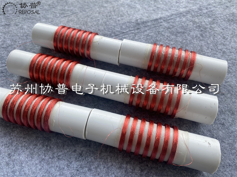
In addition, the quality of the transformer winding coil is mainly reflected in the appearance quality, which requires beautiful appearance, uniform and neat turns, no gap or overlap, and no cross or convex and concave phenomenon. In addition, it is necessary to meet the process requirements of various physical indicators, which is closely related to the performance of the transformer. It can be seen from the winding process of transformer winding coil that the performance of transformer winding machine directly affects the quality of winding coil. The transformer winding machine must be able to accurately control the process parameters, such as winding specifications, number of layers wound, number of turns per layer, etc., to achieve automatic control.
At present, compared with the domestic winding equipment and imported equipment, there is still a big gap in product performance and production efficiency, the main reasons include the selection of structural materials, machining technology and manufacturing accuracy, control principles and methods and motor quality performance.
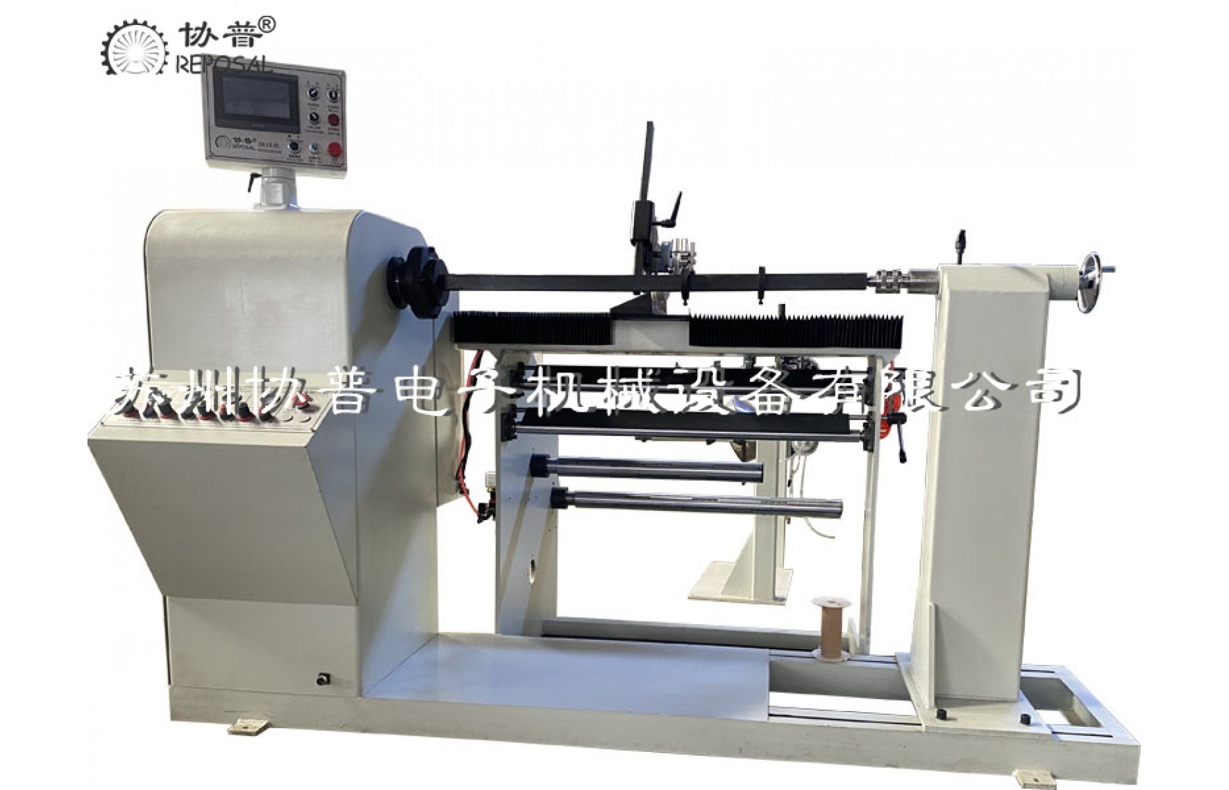
The principle scheme of the transformer winding machine is as follows: the winding die frame is clamped and positioned through the center sleeve installed on the top of the spindle box and the tail seat to ensure that there is no relative movement between the winding die frame and the clamping mechanism; The headstock is fixed on the base and cannot be moved, while the tailstock box is transversely moved through parallel guide rails to facilitate the clamping of winding die frames of different lengths. The high precision ball screw pair and guide rail are used to complete the wiring action. The ball screw driven by the stepping motor converts the circular motion of the motor into the lateral movement of the horizontal workbench, thus driving the wiring mechanism installed on the horizontal workbench to ensure that the insulated wires can be evenly arranged at a certain Angle; After the clamping position of the winding die frame, on the one hand, it rotates itself under the drive of the spindle motor, on the other hand, the wiring mechanism moves horizontally, so that the insulated wire is wound on the winding die frame, and the winding of the transformer winding is finally completed.
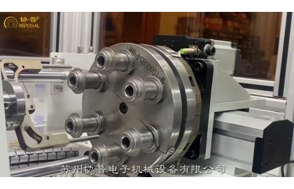
The spindle system is the core component of the transformer winding machine to realize the winding function. Its function is to provide the rotating power of the transformer winding machine, that is, to realize the winding action, and to clamp the winding die with the tail top system. Therefore, its design directly affects the functional realization and performance of the entire equipment, and its structural design will also directly affect the design of other functional modules.
The box of the headstock is welded with steel plate and section steel, and the material is Q235. The spindle drive system is composed of a main motor, a frequency converter and an electromagnetic brake, which provides the primary power for the winding action of the transformer. The traditional transformer winding machine usually uses asynchronous AC motor to drive the spindle, which will cause strong vibration when the winding machine starts and stops, and the spindle of the winding machine needs to start and stop frequently, resulting in poor tightness of the winding of the transformer and uneven tightness, which not only affects the appearance quality, but also seriously affects the performance of the transformer. The spindle motor of large transformer winding machine is driven by frequency converter, which can improve the smoothness of start and stop, thus greatly improving the accuracy of transformer winding.
![]()
According to the requirements of the compact structure principle, we need to design the spindle drive system into the planetary gear reducer and the size of the gear composed of the external flower disk structure, so that the flower disk can be connected with the spool to achieve the winding process. The output end of the motor is connected with the planetary gear reducer through the coupling, after the planetary gear reducer changes speed, the output end is directly connected to the pinion through the flat key, and then the power is transferred to the big gear, and finally the torque is transmitted to the flower plate through the big gear, to achieve the stepless speed regulation and smooth start and stop of the transformer winding machine.
The tail-top system is a horizontally movable mechanism, which is mounted on parallel guide rails and, together with the flower plate on the headstock, enables the clamping of the winding dies of different lengths. The system includes a tailstock housing, a tailstock moving system and a center sleeve.
The tail-seat box is welded with steel plate and section steel. The material used is Q235. In order to make the tail seat move, the motor provides power, and the output end of the motor is connected with the two-stage worm gear reducer through the coupling. After the worm gear and worm gear reducer is decelerated, the rotating motion of the motor is converted into linear motion through the gear and rack transmission. The upper end of the base of the transformer winding machine is installed with two sections of linear guide rail, which can make the tail seat move horizontally along the guide rail, and the rack is installed between the two linear guide rails of the base, so that when the power provided by the motor passes through the secondary worm gear reducer and the gear to the rack, the position of the tail seat can be adjusted to adapt to different lengths of the winding die frame. The base of the transformer winding machine is a T-plate structure with a stepped upper end and three holes (equivalent to trapezoidal slots) reserved at the lower end of the bottom plate. After the tail seat is adjusted in place, it can be bolted to the base through the holes reserved at the bottom.
The center sleeve is installed on the top of the tailseat box, which can be manually adjusted to extend or withdraw to facilitate the loading and unloading of the winding die frame. The center adopts a jacketed structure to fix the sleeve, which has strong clamping force, safety and reliability. The heavy rotary center is selected, which has the characteristics of high rotary accuracy and strong bearing capacity. The base of the transformer winding machine is made of steel plate and welded steel structure, which removes the internal stress and completes the whole processing at one time, ensuring that the spindle and the tail seat center are concentric, and it is also convenient for the installation of the equipment.
In order to better control the quality of large transformer winding, large transformer winding machine is designed with a clamping device, which can provide stable and adjustable clamping force in axial and radial direction when winding. The compacting device comprises an axial compacting device, a radial compacting device (with a compacting head) and a gantry beam mounted above the spindle housing and the tailstock housing.
![]()
The gantry beam adopts a concentric swing arm structure with the main shaft to ensure that the pressing head of the transformer winding machine's pressing device always compacts the transformer winding coil along the radial direction of the winding die frame. The beam is parallel to the axis of the winding main shaft, and the left and right swing arms are respectively installed on the main shaft box and the tail seat box, and there is no need to make a separate foundation during installation. The upper plane of the beam is fixed with a rack, which is snapped with the gear of the transmission system of the axial compression device, and the front side plane of the beam is installed with a linear guide rail. The swing arm can be rotated around the axis, and the rotation is controlled by a hydraulic system, through two hydraulic cylinders. The left end of the beam is fixed above the left support arm by bolts, and the right end is connected to the right support arm by a guide rail, which is easy to install the winding die frame of different lengths.
The axial compression device of the transformer winding machine can move along the beam with the winding of the transformer winding coil and provide axial compression force. It slides with the beam through the guide rail connection. Its axial movement and compression are powered by the servo motor, and the output end of the motor is connected with the precision planetary gear reducer. After the planetary gear reducer is decelerated, the power is transmitted to the rack mounted on the upper end of the beam, so that the rotating motion of the motor is transformed into the linear movement of the compression device along the beam. The axial compaction device of the transformer winding machine is fixed by the mounting plate and the radial compaction device (with the compaction head). When the compaction direction is set, the motor senses the driving compaction head through the sensor and compacts the transformer winding coil axially-according to the position change of the transformer winding coil.
Based on the safety design, the safety of the transformer winding machine is a very important performance indicator, and the safety issue is fully considered in the design of the large transformer winding machine:
The terminal position of each movable part is provided with electrical limit and mechanical limit to achieve double protection, and all the electrical limit signals of the transformer winding machine are input into the PLC to ensure that the corresponding action can be cut off in time when the limit position is reached; All motor circuits are equipped with motor protection circuit breaker matching the motor power, which can protect the motor from overload, short circuit and other aspects, and input the protection signal into the PLC to ensure that the corresponding action can be cut off in time when the fault occurs;
![]()
The fault signals of the inverter for the main shaft of the transformer winding machine and the servo drive for axial compaction are input into the PLC to ensure that the corresponding action can be cut off in time when the fault occurs; The back of the handheld touch screen has an enable switch to prevent misoperation
Related Post
REPOSAL ® winding machine Honeycomb coil winding machine
REPOSAL® numerical control honeycomb winding
machine, specially designed for honeycomb inductor coil, honeycomb coil with
its small size, small distribution capacitance, and large inductance in some
special occasions has irreplaceable. All of these excellent properties are due
to the unique structure of the honeycomb coil,
Traditional honeycomb winding machine is to
rely on a set of complex gear system to achieve the function, if you need to
wind different honeycomb coils, need to manufacture and replace different
gears, quite cumbersome and very low efficiency, REPOSAL® CNC honeycomb winding
machine uses high-precision control system, with specific algorithms, high
precision, fast speed, through different Settings can be wound different
widths, different fold points, Different number of turns of honeycomb coil, let
you wind honeycomb coil handy.
The inductance of the honeycomb coil is large,
mainly because of its special structure. After it is wound, from the
appearance, it is like a honeycomb, formed by the regular winding of coils to
form a honeycomb, in this one honeycomb, the magnetic flux of each honeycomb is
interconnected, and the magnetic flux density of these small magnets changes
with the change of time and position, just like the food in a honeycomb. This
distribution of magnetic flux pores makes the inductance of the honeycomb coil
larger, because it has more magnet interaction, thus forming more magnetic
flux, improving the permeability of the current, making the inductance
increase.
At the same time, since the magnetic flux of
each small magnet in the honeycomb coil is interconnected, the inductance can
be increased by increasing the size of the honeycomb. The larger inductance of
the honeycomb coil is due to its shape and the distribution of magnetic flux
pores, rather than due to the increase in resistance.
The insulated wire wrapped around the honeycomb
coil can be a single strand of enameled wire, or can be multiple strands of
enameled wire or silk-covered wire.
People are usually curious about how this kind
of coil is wound out, and the following is a demonstration of the CNC honeycomb
coil winding machine developed by our company.
REPOSAL ® winding machine to overcome guidance fiber wire winding process difficulties
Guidance communication has an excellent application prospect, but the guided fiber wire package needs to be wound long distance without defects, but because the surface of the fiber is smooth, brittle and easy to break, as well as the residual stress generated by the micro bending will make the signal attenuation, so it is more difficult to wind than other fibers, making long distance fast fiber automatic winding without defects has become a major issue. REPOSAL® winding machine, as a professional winding process solution provider, has been developing process research on precision winding of guided fiber wire packages for many years. Good progress has been made and REPOSAL® special winding machine for guidance fiber wire wrap developed by the winding machine can set reliable process instruction information according to process requirements and accurately execute control commands to finally finish the long distance guidance fiber wire wrap without defects. In the whole research project, we focus on solving three problems of guidance fiber optic wire wrapping system: tension control. Winding system, feeder system, and expand as follows.
REPOSAL® winding machine has successfully provided competitive solutions to the electron microscopy winding process
The main components of scanning electron microscope are electron optics system, signal collection and processing system, vacuum system, image processing display and recording system, power system and computer control system. The core part is the electron optical system, which is mainly composed of electron gun, electromagnetic condenser, diaphragm, scanning system, astigator, objective lens and various centering coils.
Reposal® winding machine As a professional supplier of precision winding solutions, we focus on the electromagnetic condenser, objective and astigmatic, because the main components are enamoured wire windings, and the precision and consistency of the windings are highly related to the image quality of the scanning electron microscope.
Electromagnetic lens coil.
The electromagnetic lens is mainly used to restrain the electron beam and it can be regarded as a convex lens in optics. Because the electron beam in a rotating symmetric magnetic field will be subjected to the Lorentz force, resulting in a focusing effect. Therefore, the quality of the enamelled wire winding coil that can generate this rotationally symmetric rather than uniform magnetic field and make the electron beam focus imaging is very important.
The enamelled wire winding coil in the magnetic lens, when the current passes through the coil, the pole shoe is magnetized, and a magnetic field is established in the heart cavity, producing a focusing effect on the electron beam. There are two kinds of enamelled wire winding in the magnetic lens, namely, the enamelled wire winding of the condenser and the enamelled wire winding of the objective lens. The lens near the electron gun is the enamelled wire winding of the condenser, while the one near the sample is the enamelled wire winding of the objective lens. General condenser is the high excitation lens enamelled wire winding, high excitation lens enamelled wire winding has many turns, a cylindrical multi-layer arrangement, requires good rotation symmetry
REPOSAL® precision winding machine
REPOSAL® precision winding machine
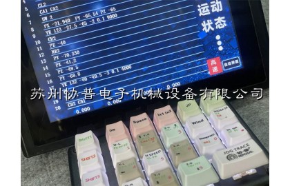
REPOSAL® Winder Releases Coded Teach Winder Control System
REPOSAL® Winding Machine Releases Code-Type Teaching Winding Machine Control System
REPOSAL® Winding Machine, a domestic coil intelligent manufacturing solution provider, has launched its new generation of code programming teaching type winding machine control system that is more open, intelligent and highly autonomous for coil winding enterprises - REPOSAL® Winding machine SP500-R5 system. Compared with the traditional dialog-type winding machine control system, the SP500-R5 system has achieved major breakthroughs in operation logic, technical architecture, and function implementation. Features.
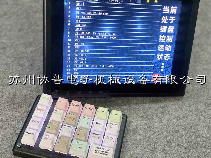
The SP500-R5 system adheres to the concept of "openness and intelligence". Based on the functions of the traditional dialog-based winding machine control system, it integrates the actual needs of the winding factory, and is committed to realizing the coil winding process programming process from the traditional parameter dialog. A major innovation and upgrade from control to code teaching programming.
REPOSAL ® winding machine has successfully realized the coil preparation process of the frameless capillary magnetic liquid acceleration sensor
In particular, the non-magnetic material in the magnetic liquid will be subjected to a magnetic field force in the non-uniform magnetic field, which makes many magnetic liquid acceleration sensors can be designed based on this characteristic.
These characteristics make the magnetic liquid acceleration sensor has many advantages compared with the traditional acceleration sensor, such as no wear, high sensitivity and simple structure.
However, most of the existing magnetic liquid acceleration sensors use solid mass blocks as non-magnetic substances, and use coils to detect changes in inductance under different accelerations to obtain output signals. However, its disadvantage is that it leads to complex magnetic circuit and poor sensor stability.
A new solution emerged -- the capillary magnetic liquid acceleration sensor, good stability, simple magnetic circuit, accurate and reliable measurement results and long service life.
Insulation tape winding machine
Insulation tape winding machine
Winding machine selection
In the narrow sense, the winding machine mainly refers to the winding machine of various enamelled wire coils, these coils may be transformers, relays, inductors, current transformers, various sensors, these coils can be seen everywhere in our lives, the common feature is to use enamelled wire winding, the difference is according to the design requirements, and the cost and efficiency requirements of industrial products, Its winding process is not corresponding, so derived from a variety of different winding machine, we show on the official website is only a part of the conventional winding machine, and some are customized, or special industries are not displayed, if you need to know, you can contact us.
Coils can be seen everywhere in our lives, such as the electric meter in the home, there are metering induction coils, trip coils in the circuit breaker, transformer coils in the community, various motor coils in industrial automation, various sensor coils, starting coils on the car, ignition coils, power motor coils on the bullet train, etc., it is no exaggeration to say that we live in a world of coils. There are so many coils, and the corresponding winding machines are different, so the winding machine is as important to the electrical world as the lathe is to the mechanical world.
There are so many types of winding machines, if you are not familiar with them, those selections have become a big problem, we now make a simple introduction from several aspects.
One is the winding method, which is generally divided into parallel winding machine, ring winding machine, and flying fork winding machine.
REPOSAL®winding machine's advantages in crossover winding machines
REPOSAL has invested a lot of R&D efforts in the field of crossover coil winding machines and has achieved a series of remarkable results.
In terms of winding accuracy, through in-depth research and optimization of the wiring mechanism and control system, REPOSAL's divider coil winding machine can control the winding accuracy within a very small error range. For example, for the wire with a thin wire diameter, the winding machine can accurately wind according to the set number of turns and arrangement, to ensure that the position accuracy of each turn of wire reaches ±0.05 mm, which greatly improves the quality and performance stability of the coil, and makes the crossover more accurate in the audio signal processing.
In terms of improving winding efficiency, REPOSAL has developed a unique high-speed winding technology. Thanks to the use of an advanced motor drive system and an efficient drive, the winding speed of the winding machine is increased by 30% compared to conventional models. At the same time, combined with the intelligent control system, continuous and uninterrupted winding can be realized, which greatly shortens the winding time of a single coil. For example, a common divider coil that used to take about 10 minutes to be wound by hand, but only 3 to 4 minutes with REPOSAL's winding machine significantly improved production efficiency and provided strong support for large-scale production.
In terms of versatility, REPOSAL's crossover coil winders are highly adaptable. By designing replaceable winding dies and flexible parameter adjustment functions, it is possible to wind a wide range of divider coils with different specifications, shapes and parameter requirements. Whether it's a crossover coil for a miniaturized audio device or a crossover coil for a large professional audio system, high-quality winding can be achieved on the same winding machine. For example, for coil skeletons with different inner diameters, outer diameters and height requirements, the winding machine can quickly switch production modes through simple mold change and parameter setting to meet diverse market needs.
In addition, REPOSAL also pays attention to the research on the convenience and intelligence of the winding machine. A concise and easy-to-understand human-computer interface has been developed, so that operators can master the operation method with only simple training. At the same time, the winding machine also has intelligent fault diagnosis and early warning function, which can monitor the parameters in the winding process in real time, and once there is an abnormal situation, such as wire breakage, abnormal winding tension, etc., it will immediately send out an alarm and prompt the cause of the failure, which is convenient for the operator to deal with in time and reduce the risk of production interruption and equipment damage.