Process requirements of traction motor winding machine
Process requirements of traction motor winding machine:
Traction motors are mainly used for railway mainline electric locomotives, industrial and mining electric locomotives, electric drive diesel locomotives and various electric vehicles (such as battery cars, urban trams, subway electric vehicles).
The constraints of the coil during the winding process of the winding machine mainly come from two aspects: design requirements and craftsmanship. The specific manifestations are:
The structural design of coils and windings must not only meet the requirements of electrical performance and temperature rise limit, but also pay attention to the applicability of existing winding machines, the economical and reasonable use of electromagnetic wires and insulating materials, simple structure, and convenient manufacturing. Good manufacturability. In order to achieve better manufacturability and reliability, there are some control points that must be considered in the early stage. For this type of problem, REPOSAL® winding machine shares some content with you.
1 Arrangement of forming coil wire
The winding of the formed coil wire is shown in Figure 1. The single-row single-row as shown in (a) or the double-row double-row as shown in (b) is convenient to wind, and the insulation between turns is not easy to be damaged. The design should be used as much as possible This arrangement. It is difficult to manufacture a single double row as shown in Figure (c). In order to prevent the turn-to-turn voltage from being too high, each row must be transposed. Although there is additional insulation at the transposition, the turn-to-turn insulation is still the most vulnerable. However, production practice has proved that the scrap rate of this type of coil is very high. The arrangement of Figures (d) and (e) is only transposed once, or the two rows are respectively wound by a winding machine and connected at the nose end to avoid damage to the insulation between the turns, but the voltage between the rows is higher, which must be considered Additional insulation.
4 4 4 8 7 4 8 4 5
3 3 3 5 6 3 7 3 6
2 2 2 4 3 2 6 2 7
1 1 1 1 2 1 5 1 8
(a) (b) (c) (d) (e)
figure 1
2Choice of wire and insulation material
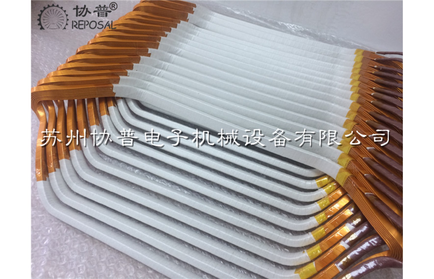
In the winding process of the winding machine, the cross-sectional dimension of the insulated flat wire, the ratio of thickness to width is about 1:2. The wire that is close to the square is easy to twist when winding; the edge of the wire is too flat when the coil is stretched. It is easy to lift and damage the insulation between turns. Insulation of flat conductors generally adopts double-glass-fiber coating or double-glass-fiber enameling. For example, double-glass-fiber enameling still cannot meet the requirements, and it is best to use thin-film wrapping.
A Nomenm paper (an aromatic polyamide tape containing 50% powder mica) has been developed abroad to longitudinally wrap insulated flat conductors for medium and large motors. The wire insulation is thin and reliable, and can reduce the workload of coil manufacturing and reduce the cost.
Nomenn paper only uses one layer, 0.08 mm thick, and the paper tape wraps the two narrow sides and one wide side of the wire. Because the second wide side faces the adjacent circle, there is no corona, so in principle, no corona protective layer is needed, leaving a longitudinal slit on this wide side will not cause the enameled wire to deteriorate. At the top (or bottom) of the coil side, this slit faces the main insulation, and since the slit is only about 0.08 mm, the first mica layer and resin of the main insulation can completely fill it.
The bending radius of the flat-wound magnetic pole coil is related to the width and thickness of the ribbon wire. Too small a radius will cause cracks on the outer edge of the ribbon wire. According to actual experience, the allowable minimum bending radius R is shown in formula (1):
R=0.05b2/a┄┄┄┄┄┄┄┄┄┄┄┄┄┄┄(1)
In the formula, a and b are the thickness and width of the ribbon wire, generally a:6=1:15 and below.
The diameter of round copper wire used for soft winding should generally not be greater than 1.56 mm, and the maximum should not be greater than 1.68 mm. Because the thick wire is too hard, it is difficult to wind and embed the wire, but if the number of windings is increased, the space of the wire slot will be used. At the same time, the smaller the wire diameter, the higher the price per unit weight. Therefore, these aspects should be analyzed and compared during the design.
Magnet wire insulation layer and insulation material are subject to mechanical force during wire embedding, etc. When selecting materials, it is necessary to leave a necessary margin for its mechanical strength according to the different characteristics of the winding. At the same time, the compatibility and cost between them must be considered; materials from difficult sources should be avoided as much as possible.
Motor windings now tend to reduce the insulation thickness and reasonably improve the heat resistance level. When designing an insulating structure, films, glass fibers, and synthetic fiber products should be used first; when mica products are needed, powder mica should be considered first.
3 wire slot filling
In terms of the full utilization of the effective materials and the running performance of the motor, it is better to fill the coils tightly. Too loose filling may cause the wire to move in the slot, the insulation is easy to damage, and the thermal conductivity is poor; but the wire slot is too tight, which will cause embedding. It is difficult to wire, which significantly increases the amount of labor for inlay assembly, and it is easy to damage the insulation.
When designing the soft winding, the selection of the winding machine and the selection of the slot full rate should be determined based on the characteristics of the core slot shape and production experience. Generally take 75~78%, not more than 80%; 2-pole motors should not be more than 75%. Under the same circumstances, the slot full rate of the rotor winding can be slightly higher than that of the stator winding. For the design of open slot and semi-open slot shape, appropriate assembly gap should be reserved according to the size of the coil. The bilateral gap is generally about 0.4 to 0.6 mm.
4 end elongation
Reducing the end elongation can save the magnet wire and reduce the resistance loss, but the end extension size is too short will cause the embedding and end shaping difficulties. As a result, the possibility of short-circuit between turns increases. The end elongation of the double-layer winding varies greatly with the winding pitch (or number of poles), while the end elongation of the concentric winding with the same pitch does not change much, so that motors with different numbers of poles can use the same end cover parts .

