The choice of the number of turns of the CNC winding machine controller
heading_title

Choice of winding number counting unit:

        The winding count unit can be selected. The number of turns on the display is composed of 5-digit digital tubes. When the default turn count unit is 0.1 turns, the maximum number of turns that can be set by this controller is 9999.9 turns. When the counting unit is changed to 1 circle, the maximum number of circles can reach 99999 circles.
        
        The following other parameters are set in the same way, please refer to:
7.1. Operation mode selection
 The factory setting is [10010100].
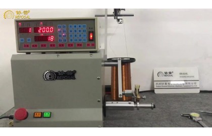
 When entering the operation mode selection state, the step sequence display and the data display display the eight-digit operation mode setting value. If you want to change the setting, please press the fixed value first, and the modification completion button will light up the decimal point. You can press the buttons from right to left to return to the standby state.
 number keys to modify its settings
The eight digits represent eight operating mode options, as follows:
1. Cylinder action: 1 is action, 0 is no action.
         1 is action; 0 is no action.
2 output mode: Winding shaft operation signal output mode,
        0 is CW=forward rotation start, CCW=reverse rotation start; 1 is RUN=running start, F/R=forward and reverse rotation switching.
3 Zero point selection: winding axis zero point and circle count mode selection,
        0 means that there is zero point, and it is absolute counting mode; 1 means that there is no zero point, and it is relative counting mode at the same time;
        2 means that there is zero point, and it is relative counting mode; 3 means that there is no zero point, and it is absolute counting mode at the same time.
4 Deceleration at both ends: When the position of the spool is close to the width boundary, whether to decelerate the spool,
        0 means no deceleration; 1 means to decelerate.
5 Braking mode: When the winding speed is changed from high to low speed, choose whether to make short-term braking,
        0 for no braking; 1 for short braking.
6 lap units: When the data display displays the laps, the lap count unit is selected.
        0 means 0.1 circle; 1 means 1 circle; 2 means the display unit is 0.05 circle.
7 units of dimension: metric or inch unit selection for cable rod screw,
        0 is metric (mm); 1 is imperial (inch).
8 Start modes: Foot (external start) switch operation mode selection,
        0: Single start, the foot switch must be ON all the time after starting, if the foot switch is released, the operation will be suspended;
        1: It is a double start. After starting, release the foot switch to continue running, and press the foot switch again to suspend operation;
        2: Press the start switch to run at a slow speed, release the switch to run at a constant speed;
        3: Press the start switch to run at a fixed speed once, and then press it again to run at a slow speed;
        4: Press the start switch to execute constant speed operation.

Related Post

Switching-and-debugging-between-two-programs

Switching-and-debugging-between-two-programs

Switching-and-debugging-between-two-programs

Mechanical Tensioner Guide

Mechanical Tensioner Guide

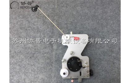
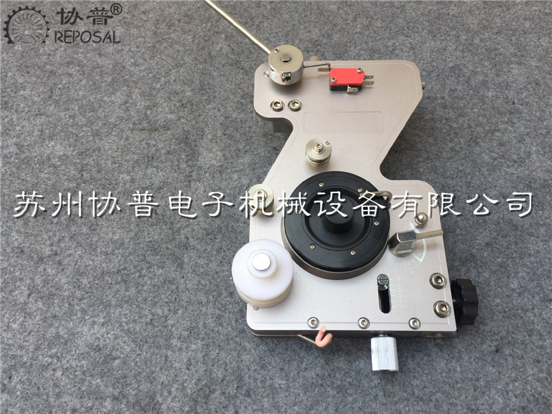
      Let's now look at the tensioner, a threading process. First, the enameled wire passes through the ceramic ring at the bottom of the tensioner, and then passes through the wool felt above it. The clamping degree of the wool felt can be adjusted by passing the knob on the other side of the tensioner.

      Then go through the anti-jumper, and then go over the damping wheel on the tensioner once again, then pass through an anti-jumper again, and then pass through the guide wheel on the fishing rod, this is the threading process.

      Then how do we adjust to a more appropriate tension?   


       Let's take a look at the first one now. This handle is a tension switch. When the tension switch hits the top, the damping wheel doesn't work. When it is turned, it becomes very light. When the tension switch hits the bottom, the tensioner starts to work.

      If we want to increase the tension, we adjust the knob under the bottom of the tensioner, there is a scale in this position. Through this, adjust the damping size of the damping wheel on the tensioner.

      Then the handle at this position is used to adjust the back tension, which is the force of the fishing rod to bounce back. The general principle of our adjustment is that during the winding process, the fishing rod will not become weak under the interaction of the damping wheel. Sagging down, it will not be too strong and only a good swing requires a relatively large swing range, so that it can buffer and at the same time play a role in tensioning the enameled wire.

Video instructions for use of toroidal transformer winding machine

Video instructions for use of toroidal transformer winding machine

          Suzhou REPOSAL Electronic Mechanical Equipment Co., Ltd. specializes in providing: toroidal transformer winding machine, current transformer winding machine, voltage transformer winding machine, ring voltage regulator winding machine, inductance coil winding machine, iron core chamfering machine , Parallel winding machine and other coil processing equipment and winding machine accessories.

       The company has the advantages of R&D and production of the entire plant of electronic transformers and transformers. It is different from many assembly manufacturers in the industry. We have gathered many engineering and technical personnel in the winding machine industry. After many years of research and development and production experience, we have developed a new generation of series winding. Equipment, especially toroidal winding equipment, is widely used in manufacturing industries such as toroidal transformers, transformers, voltage regulators, inductive coils, etc., and has received many praises from the industry; Customers provide more professional and quality products and services.

Toroidal coil winding machine operation video-Machine operation

Toroidal coil winding machine operation video-Machine operation

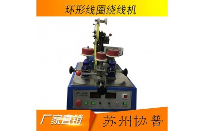
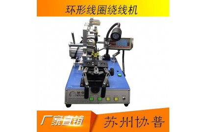
       Below we introduce the structure of this toroidal coil winding machine. This part is the controller and this part is the clamping base. We control the product clamping by opening and closing the handle. This position is the storage ring. The enameled wire is stored on the storage ring first, and then wound around this product. This position is a manual winding handle. Turn this handle. The steel plate can be driven manually. The steel ring has an opening. This position is an opening. The opening is opened and closed by sliding the handle up and sliding to the left. . This position is called the crimping plate, and this position is called the baffle. After the line is removed, its degree of tightness is determined by the tension of the belt. The tension of the belt is adjusted by the tension adjustment knob. When adjusting the tension of the belt, first loosen this And then rotate the handle. When rotating the handle, there is an idler wheel. When the idler wheel goes in, the tension of the belt will increase, so that the winding of the enameled wire will become tighter.

Operation video of belt loop coil winding machine-controller setting

Operation video of belt loop coil winding machine-controller setting

Operation video of belt loop coil winding machine-controller setting

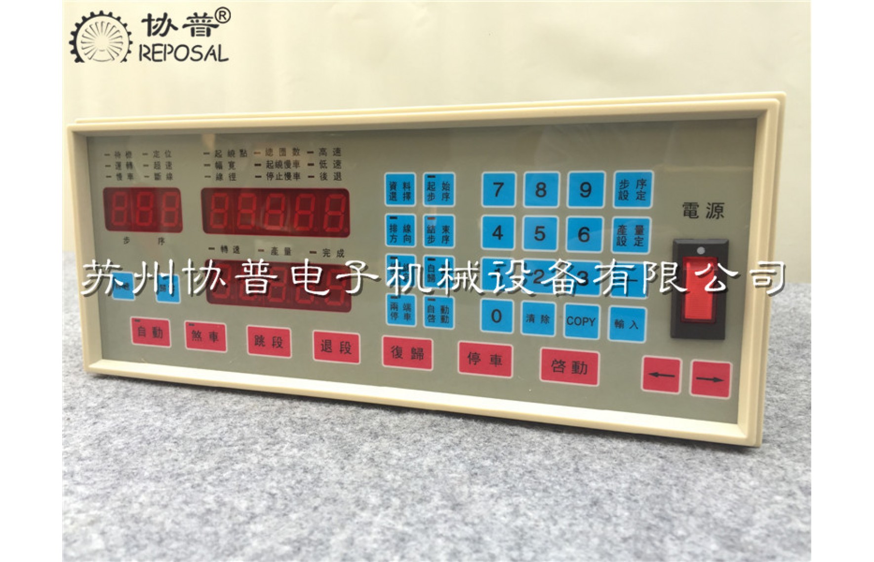
     Now we focus on the use of the controller of the toroidal coil winding machine. The controller is very mature. It is divided into several functional areas. This one is the status area. For example, the indicator light before the standby character is on, which is standby. Status, the red light in front of the standby is on. For example, when we press Start, the running light will turn on, indicating that it is currently running. This is a status area.

      This is a numeric parameter. When we want to set the parameters of the toroidal coil winding machine, for example, the parameters such as the diameter of the outer diameter and the diameter of the enameled wire, there is still a cable angle for the ring-shaped product. From this position to this position slowly, this involves a range. We use the winding angle and the cable angle to control the cable range on the controller interface, after the specified cable angle , He went back to the line, before and after the set winding angle and line angle.

     The other is the speed. The high-speed and low-speed reference on the controller interface of the loop coil winding machine. The high-speed refers to the normal winding speed. The low-speed is the speed at the beginning and the end, and then the number of slow-down laps. Specify a specific number, such as slow speed, you need to specify a lap speed of one lap, two laps and three laps, according to your needs.

       Here is a switch parameter area, such as the direction of the winding, such as the storage ring on this toroidal coil winding machine, we can let him turn clockwise or counterclockwise, and then the direction of the cable, the cable The direction is the process of winding the product. We can also let him turn clockwise or counterclockwise. This is the direction of the cable. Whether to start automatically between different programs, this can also be set.